
MRF Waste Management
Materials Recovery Facilities that separate dry waste into clean, saleable commodity streams.
What is a Materials Recovery Facility?
An MRF is the point where mixed dry waste stops being a disposal problem and starts being a revenue stream. Incoming material is fed onto a controlled line where mechanical and manual sorting stages progressively separate paper, cartons, PET, HDPE, films, ferrous and non-ferrous metals and glass.
The output is baled, graded commodity that recyclers will actually pay for — and a residual fraction small enough to be economically routed to RDF rather than landfill.
How we design an MRF
We size the line to your daily tonnage and expected composition, then choose the sequence of separation stages that reaches your purity targets with the fewest manual pickers.
Ergonomics matter as much as machinery: picking cabin height, belt speed, lighting and chute placement all determine whether the designed recovery rate is achieved in practice.
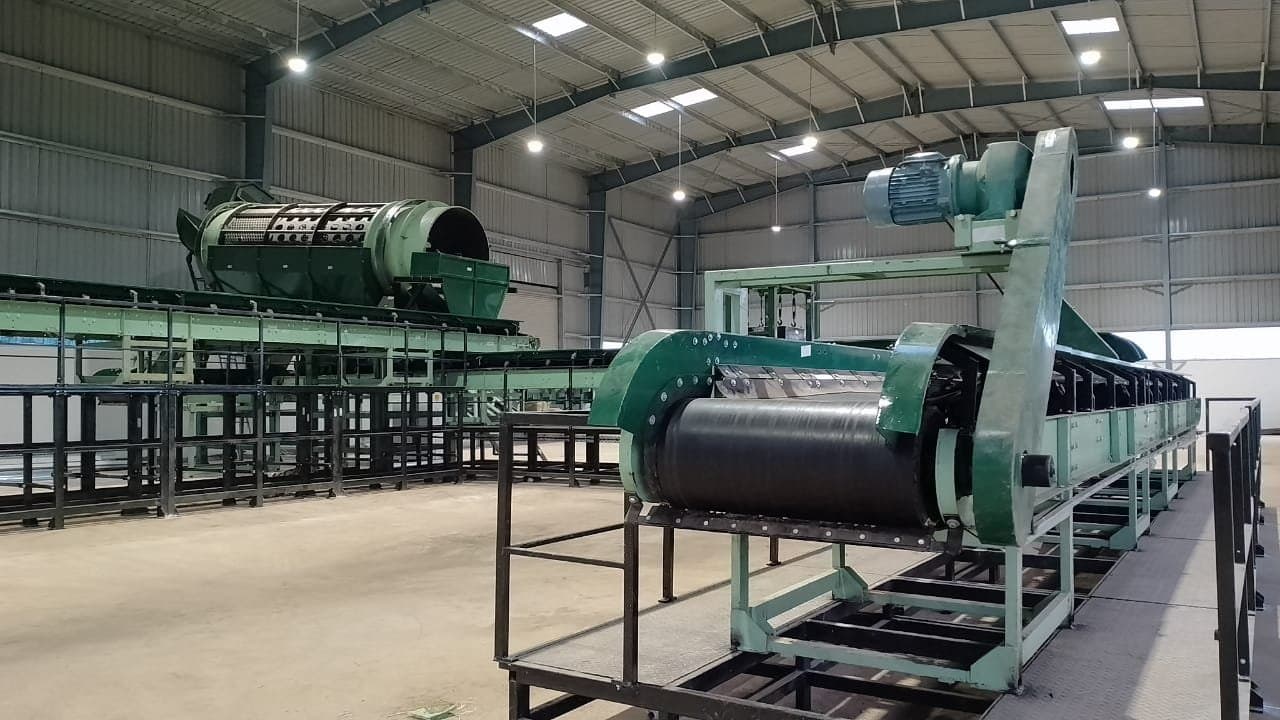
Core MRF equipment
Bag Openers
Open incoming bags without shredding the contents, preserving the quality of recoverable material.
Trommel Screens
Size-based separation that removes fines and splits the stream into manageable fractions.
Picking Conveyors
Ergonomic sorting platforms with chutes and bunkers positioned for sustained picking rates.
Air Density Separators
Split light films and paper from heavy rigid material using controlled air classification.
Magnetic & Eddy Current Separators
Automatic recovery of ferrous and non-ferrous metal without manual handling.
Balers
Compact sorted commodity into transport-efficient, market-ready bales.
Benefits of a well-designed MRF
- Higher commodity purity means better prices from recyclers.
- Sharp reduction in the volume of waste sent to landfill.
- Predictable, measurable recovery rates for reporting and compliance.
- Creates structured, safer employment for sorting staff.
- Residual fraction feeds directly into RDF production.
- Modular layout allows capacity to be expanded in stages.
How It Works
Process & mass flow for a Materials Recovery Facility
Mixed municipal waste enters once and leaves as four graded streams. Each trommel stage takes a size cut, and every cut gets its own sorting and separation train.
- Process stage
- Saleable output
- Residue / reject
Screen apertures and stage count are configured to your waste characterisation — this layout is indicative.
Let's come together to make cities clean, and farms green
Talk to our team about your waste processing requirement — we will get back to you within one working day.